Tuesday, June 30, 2015

16: Battery Backup
Post 11 corrected
** revised again 7/16/15 **

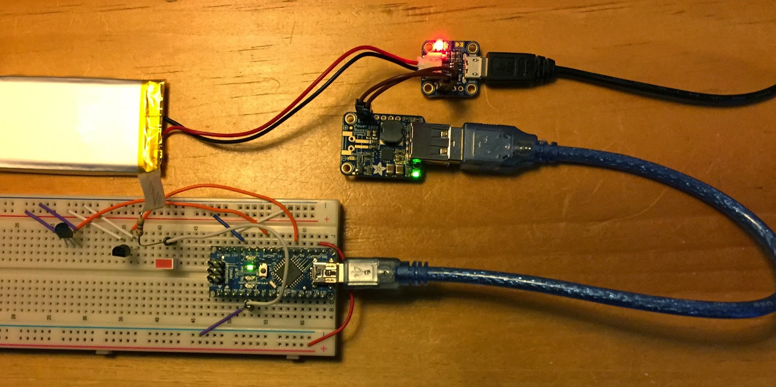
When I tested my battery backup circuit (post 11) I failed to let the systems run on both USB input and battery for long enough. Turns out with 5V/1A input from my USB hub the setup drains the battery. And when that happens the USB output drops to 4.10V. Not nice. However, USB input of 2.1 Amps seems to correct the problem.  Wrong again: Anyway, the setup pictured only works if the USB out draws less than 500mV. None of my Nano test setups take this little -- nor does my Particle Core. So regardless of 5V USB input the the system fails when the battery runs down (USB output drops to 4.1V).

Gory details at http://forums.adafruit.com/viewtopic.php?f=15&t=76014


Most USB hubs don't provide 2.1A outputs. So I ordered a 5-pack of 2.1A wall plugs. I'll let you know how they work long-term.

Saturday, June 13, 2015

15: Soil Moisture Sensor: Arduino and Particle Core
-- revised --

I programmed this first on an Arduino Nano. Pretty easy. My guesses at wiring did no damage. The "sunkee soil hygrometer" (probably meant "hydrometer") was mostly marked in Chinese. One tricky part: once you start the program the probe device is on all the time -- drawing current. I first considered turning it on & off with a transistor. But then I wondered, why not just use a digital pin. I don't know if this is as safe, but it's simple and it works. In addition to short patch wires, I tested this using a 50' CAT5 cable between the probe and the interface. It worked fine. See post 27 at http://dicks-raspberry-pi.blogspot.com/.

I had expected these things to be bigger. 
Probe points only about 2" long.
Adjustment screw only useful for digital (ON/OFF) output.

Here's my Particle Core code. The Core can be read anywhere wifi is available (if you know the codes). So the Core can be remote from my Raspberry Pi control program.

/* device: "sunkee soil hygrometer" [SP?]

2 wires from probe "YL" & "69" (?) to interface board 
  no-label<->(YL) & GND<->(69?)
4 wires out to Arduino: "VCC" "GND" "D0" "A0"

Arduino or Particle/Core -- just guessing:

VCC -- 5v (or 3.3) 
  Arduino 5v: analog range=1023:200 (10 bits), 
  Core: analog range=4095:2000 (12 bits)
GND -- GND
D0  -- unused: just on/off
A0  -- analog pin
*/
int soil = A3; // read the device
int power = D1; // turn power on just for the reading

void setup() {
    Spark.function("soil1", Soil); // Core-only function
    pinMode(soil, INPUT);
    pinMode(power, OUTPUT);
    digitalWrite(power, LOW);
}

void loop() {
    // not used
}

int Soil(String command) {
    digitalWrite(power, HIGH); // turn probe on
    delay(200); // let it settle?
    int raw = analogRead(soil); // high=dry, low=wet
    delay(200);
    digitalWrite(power, LOW); // turn probe off
    int read = map(raw,4095,2000, 0,20); 
    return read; // return reading between 0 & 20
}

Thursday, May 14, 2015

14: Spark is now Particle (?)

See
http://spark.cmail1.com/t/ViewEmail/t/2CCE5B6961CA5D4E/9BDBDA8F3EFB0BE0C67FD2F38AC4859C

They say 681 other trademarks created confusion. Maybe. Maybe someone offered to sue them. Still very interesting company.

(why not "webino" or "cloudino")

Sunday, May 3, 2015

13: LED Bar Graph

I bought 3 of these from All Electronics (as I recall). $.50 each.
I assumed these were a 1-piece item, but nope:
note the +/– markings
Each separated LED is dimly marked too:
Too bad they didn't build the ground-side resistors in. Otherwise, the 2 pins neatly fit in adjacent breadboard rows -- and make for tidy wiring.

Wednesday, April 29, 2015

12: Device Review
Apr 25, revised: May 2, Aug 1, Nov 25, 2015

Devices I've wired/programmed* for the Raspberry Pi, Arduino and Spark Core (now Particle Photon)
  • LEDs (everyone starts with these) - RAS
  • Push buttons - RA
  • PIR motion detector - R
  • Magnetic door sensor - RAS
  • Photosensor RAS
  • DS18B20 temperature sensor - RAS
  • DHT22 temperature/humidity sensor - RAS
  • TMP36 temperature sensor - AS
  • Raspberry Pi camera (B/W conversion, timelapse, security cam) - R
  • Relay Switches - RS
  • Water sensor - R
  • Soil moisture sensor - AS
  • Water valve/solenoid control - RS
  • Rangefinder: ultrasonic, IR (several models) - RA
  • Speakers - RA
  • CO gas sensor - A
  • Natural gas/propane sensor - A
  • Mini vibrating motors - A
  • Pi - Arduino Com over USB - A to R
  • RF (radio frequency) read & write - A to R
  • RFID sensor - AS
  • 16x2 LCD text device - RA
  • 7-segment clock device - R
To make the above work--
  • resistors, capacitors, diodes, transistors, 
  • Darlington array - R 
  • I2C (MPC2308) - RS 
  • MPC3008 (analog) - R
  • PWM - A
  • Backup battery setup - RAS
  • Also: Internet upload/download, email, text message - RS
* Programmed in Python, C, C++, Linux Shell, Crontab

Tuesday, April 7, 2015

11: Uninterruptible Power (the other UPS) for Arduino, Spark Core or Raspberry Pi
* revised Apr 17, 2015 *

There seems to be precious little help on line for this even though it turned out to be pretty easy. I watched --

I got my parts from Adafruit (charger: $6, powerboost: $15, 1200mAh battery: $10, plus their irritating shipping charges).


I tested this with an Arduino Nano--
both external power and  battery (note red LED*)

And with my Spark Core--
just battery

You can connect/disconnect the battery any time. And this will work for Raspberry Pi just as well (REVISED: probably, if the system doesn't draw more than 1000mA -- see dicks-raspberry-pi.blogspot.com/).

Also REVISED: When I let the Spark run until the battery ran down there was a problem: The Powerboost didn't just quit cleanly. The boost/Spark stopped/restarted, stopped/restarted (voltage hiccups?). I suppose that when the boost stopped drawing current then the battery recovered a bit. Anyway: not nice. The Powerboost has an Enable pin (labeled (EN). Grounding that will stop things cold. Then how does it restart? What un-grounds the EN? See * note below. Kudos to Spark that the Core survived undamaged! Note: the Powerboost did not survive (Adafruit replaced it).

Considering the way that (non-hobby) "programable controllers" are used, I'd think that a UPS setup like this would be about Arduino Lesson 3!

___________
* If you aimed a photo resistor ($1) at the charger's red LED external power indicator then you could detect power failure and shutdown gently (but HOW and HOW-TO-RESTART?).

Tuesday, March 31, 2015

10: Spark Core Battery Drain

I don't have a meter on input but the 12,000mAh battery shown in the post 9 image is only down 25% after about 30 hours. The same battery will only run a Raspberry Pi model B (and similar devices) for about 24 hours.